Contact us

Decade Counter Using CD4017IC Full Making IC PROJECT

500.00

Availability: In Stock
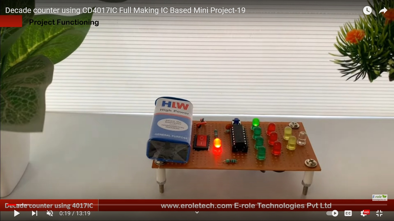
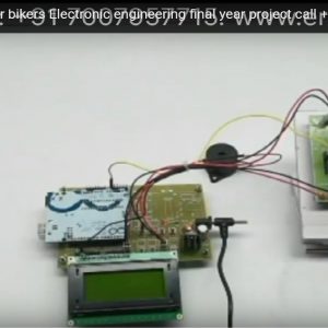
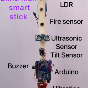
Circuit Design:

  1. CD4017 Connections:
    • Connect the VDD pin (pin 16) of the CD4017 IC to the positive supply voltage (e.g., 5V).
    • Connect the VSS pin (pin 8) of the CD4017 IC to the ground (0V).
    • Connect the Clock Enable (CE) pin (pin 13) to the positive supply voltage (e.g., 5V).
    • Connect the Reset (RST) pin (pin 15) to the ground (0V).
    • Connect the Clock (CLK) pin (pin 14) to the output of a 555 timer or another clock source.
  2. Decoding and LED Connections:
    • Connect the Q0 to Q9 outputs (pins 3 to 11) of the CD4017 to the anodes of LEDs.
    • Connect the cathodes of the LEDs to ground through current-limiting resistors (e.g., 330Ω).
  3. Clock Source (e.g., 555 Timer):
    • Connect the output of a clock source, such as a 555 timer IC, to the Clock (CLK) input (pin 14) of the CD4017.
  4. Capacitor for Debouncing:
    • Connect a capacitor (e.g., 100nF) between the Clock (CLK) input (pin 14) and the ground to debounce the clock signal.

Working Principle:

  • The CD4017 is a decade counter with 10 decoded outputs.
  • The counter advances its output one step at a time with each clock pulse.
  • Each output corresponds to a binary count from 0 to 9.
  • The clock source generates pulses to the Clock (CLK) input, causing the counter to advance.
  • The decoded outputs can be used to drive LEDs or other components to indicate the current count.

Product Description

Reviews

There are no reviews yet.

Be the first to review “Decade Counter Using CD4017IC Full Making IC PROJECT”