Connect the VCC pin (pin 8) of the 555 timer to the positive supply voltage (e.g., 9V).
Connect the GND pin (pin 1) of the 555 timer to the ground (0V) of the circuit.
Monostable Mode Connections:
Connect the trigger input (pin 2) to the junction of the resistor and capacitor in series.
Connect the threshold input (pin 6) to the discharge pin (pin 7).
Connect the discharge pin (pin 7) to the capacitor side of the resistor-capacitor series.
Resistor and Capacitor Values:
Connect a resistor (e.g., 10kΩ) from the trigger input (pin 2) to the positive supply voltage.
Connect a capacitor (e.g., 10μF) from the trigger input (pin 2) to the ground.
Connect the other end of the capacitor to the discharge pin (pin 7).
Potentiometer Adjustment:
Connect a potentiometer (e.g., 10kΩ) between the threshold input (pin 6) and the positive supply voltage.
Connect the wiper of the potentiometer to the discharge pin (pin 7).
Feedback Diode:
Connect a diode (1N4148 or similar) from the discharge pin (pin 7) to the junction of the resistor and capacitor.
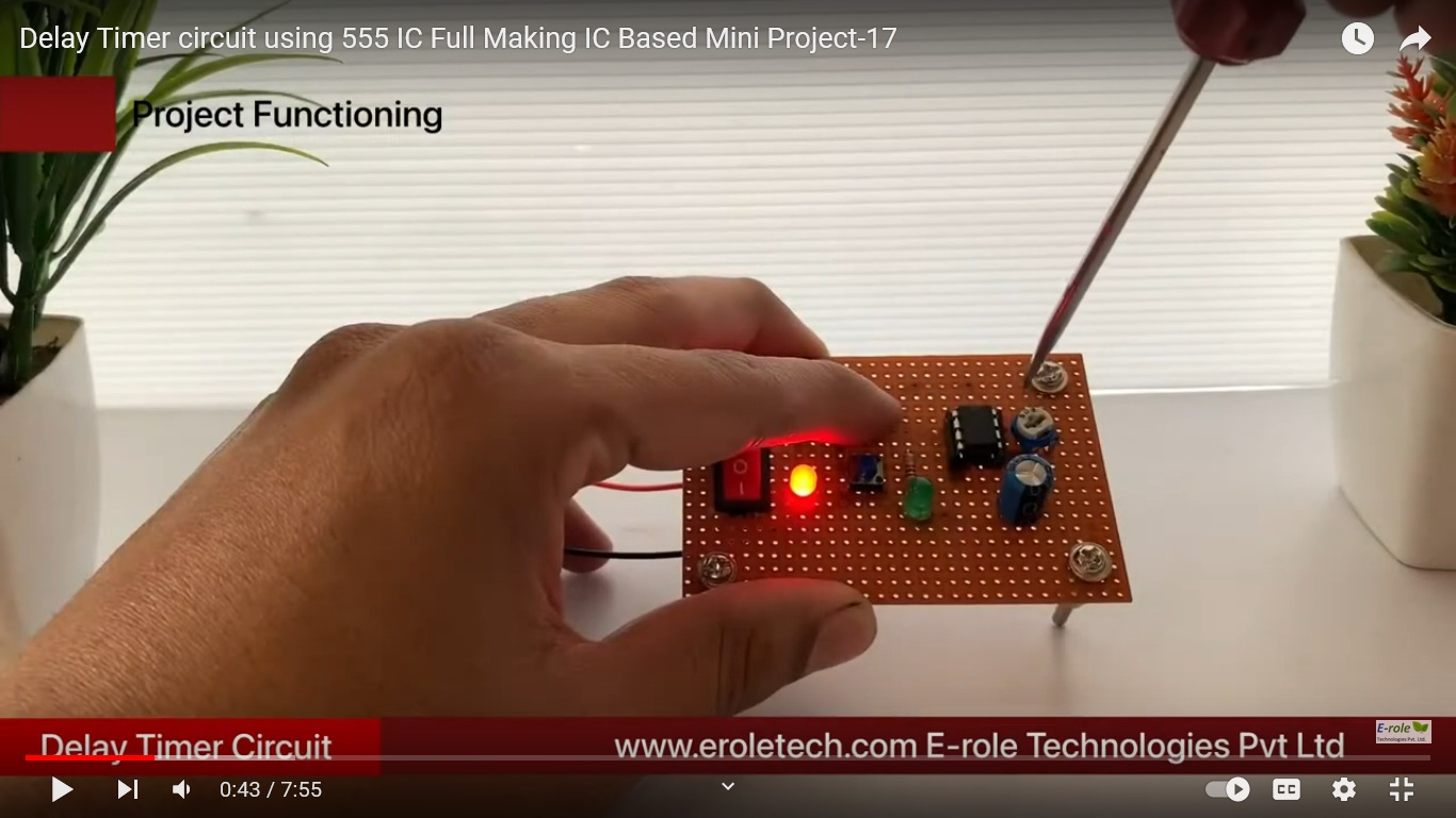
LED Indicator:
Connect an LED in series with a current-limiting resistor (e.g., 330Ω) from the discharge pin (pin 7) to the ground. This will serve as an indicator for the timer output.
Normally Open Push-Button:
Connect a normally open (NO) push-button switch from the trigger input (pin 2) to the ground. This is used to trigger the timer manually.
Output:
The output is taken from the discharge pin (pin 7) of the 555 timer.
Working Principle:
When the push-button is pressed, the capacitor charges through the resistor and potentiometer until it reaches the threshold voltage, triggering the 555 timer.
The timer then enters a monostable state, and the discharge pin goes high.
The LED lights up during the timing period, determined by the values of the resistor, capacitor, and potentiometer.
After the timing period, the output goes low again.

Reviews
There are no reviews yet.