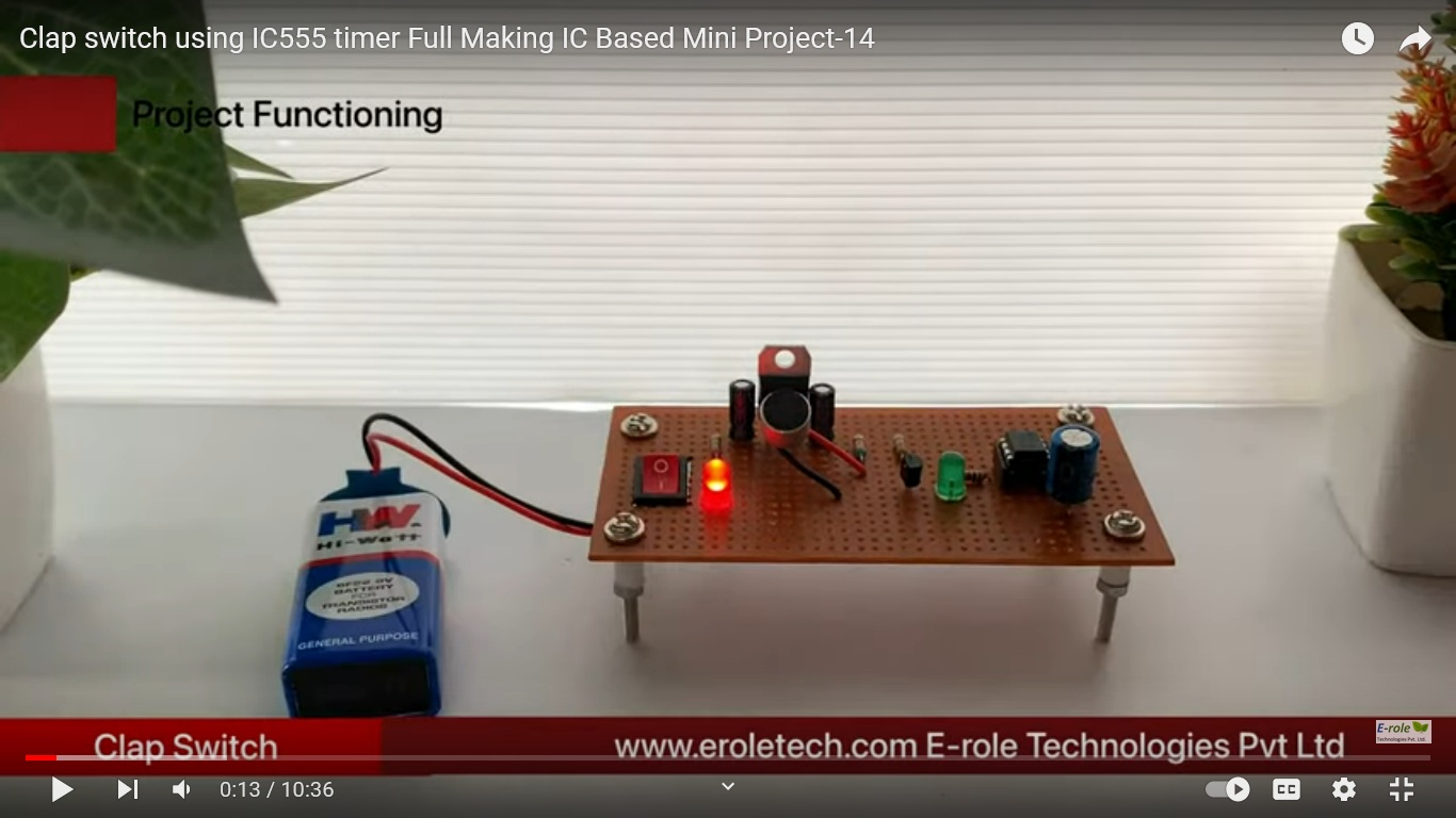
The IC555 timer is configured as an astable multivibrator. It generates a continuous square wave output.
Microphone or Sound Sensor Module:
The microphone or sound sensor module is used to detect claps or sudden sound changes. It produces a voltage variation in response to sound.
Resistor (R1):
R1 is connected between the positive voltage rail and the discharge pin (pin 7) of the IC555. It is used for biasing the IC.
Resistor (R2):
R2 is connected between the discharge pin (pin 7) and the threshold pin (pin 6) of the IC555. It is used for discharge.
Capacitor (C1):
C1 is connected between the threshold pin (pin 6) and the discharge pin (pin 7) of the IC555. It is used for timing the circuit.
Resistor (R3):
R3 is connected between the threshold pin (pin 6) and the control voltage pin (pin 5) of the IC555. It is used for sensitivity adjustment.
Diode (D1):
D1 is connected between the relay coil and the positive voltage rail. It is used to protect the IC from reverse voltage generated when the relay coil is turned off.
Relay Module:
A relay module is used to control the appliance. The IC555 activates the relay, allowing it to switch the appliance on and off.

Reviews
There are no reviews yet.